The Flame Analysis Unit-FAU810

The Flame Analysis Unit or FAU810 is ABB's latest cutting-edge flame analysis device. FAU810 is designed from scratch, with maximum flexibility, availability, and reliability. It utilizes the latest technology to make flame analysis as cost-effective as possible, while maintaining ABB's rock solid reputation as the most reliable instrument in the industry.


FAU810 is easy to install and configure, flexible to operate, and uses redundant Profi bus DP-V1 or standard Modbus interface for secure data exchange and adjustment. You can connect any type of ABB flame sensing device to FAU810. This makes FAU810 the standard module for all ABB flame scanner applications and the preferred solution for retrofitting existing installations.
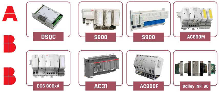


ABB SERIES


FAU810 specification

Each flame analysis unit consists of two independent channels. Each channel can receive and process flame detector signals. These two

detectors can be combined arbitrarily

The following design:

SF810 flame scanning head

All DFS Flame scan heads

Flame rod (ion flame monitoring)

Each Detector is independently configurable from the FAU810 pushbuttons and display, with Flame Explorer engineering tool or

via Profibus.

The FAU810 can be powered by a single or redundant 24 VDC source (+/- 20%).

The FAU810 has built-in diode auctioneering for power source isolation.

Two digital input channels are available for remote parameter switching. One digital input per sensor.

(Example: Parameters for a dedicated Flame Detector may be tailored to monitor either coal or oil firing)


More recommended spare parts

F650BABF1G0HIC

DIMA3-ES-16-MINI

UG440H-TH1

RFU630-13105

BH2114*452831533

1404-M805B-ENT

6SN1118-0DJ21-0AA2

CDE34.006.W2.4.PC1

V812iS

BMI0702T06A

IS7200-01

BKSC-4015GS1B-C

V808iSDY

4PP045.0571-042

312SC VIPA 312-5BE03

6SE7013-0EP50-Z

SPD 3.200-A1-1

RYG1.1HA-LP

A5E00023809 A5E00054897

6SN1118-1NJ00-0AA2

A5E00747065

4B1270.00-K15

CACR-JUM25A2A

MMI-4067AN-R1A160CF2CE6.0

CACP-JU051D2A

SPBA-24D24D120LF

CACR-JU028A2A

1FL6061-1AC61-0LH1

CACP-JU15A3A

IM308 6ES5308-3UC21

CACP-JU22D3A

JM-603-480-SB1

VSXC100M03X00EP

PM583-ETH 1SAP140300R0271


Contact Yuki now

Email: sales6@askplc.com

Skype: +86 17359287459


WhatsApp+86 17359287459

Moore Automation Products Paving the Way for Intelligent Industry

In the era of rapid technological advancement, Moore Automation Products has

emerged as a leader in the field of industrial automation. With a focus on innovation

and quality, their products are designed to meet the evolving needs of modern

industries. From smart sensors to advanced control systems, Moore offers a

comprehensive range of solutions that are transforming the way businesses

operate.


One of the key features of Moore Automation Products is their reliability. Built to

withstand the harsh conditions of industrial environments, these products are

known for their durability and long lifespan. Whether it's a high-temperature

manufacturing plant or a corrosive chemical facility, Moore's products can be

trusted to perform consistently and accurately.


Another aspect that sets Moore Automation Products apart is their user-friendly

design. With intuitive interfaces and easy-to-use controls, these products are

accessible to both experienced engineers and novice operators. This not only

simplifies the integration process but also reduces training time and costs. As the

demand for automation continues to grow, Moore Automation Products is poised to

play a crucial role in shaping the future of industry.


Honeywell 05701-A-0285 PC Board: Precision Engineering for Optimal Performance


The Honeywell 05701-A-0285 PC board is a remarkable piece of technology that

stands out in the world of industrial components.


Crafted with precision and attention to detail, this PC board offers exceptional

reliability and performance. It is designed to handle the most demanding

applications, ensuring seamless operation and consistent results.


The 05701-A-0285 is engineered to meet the highest standards of quality, making it

a trusted choice for professionals in various industries. Whether it's for

manufacturing, automation, or other critical processes, this PC board delivers.


With Honeywell's reputation for innovation and excellence, you can be confident

that the 05701-A-0285 PC board will provide the performance and durability you

need. Discover the power of this remarkable component and take your operations

to the next level.


Unraveling the Excellence of ABB 1TGE102009R2300 Control Unit


In the realm of industrial automation, the ABB 1TGE102009R2300 Control Unit

stands out as a true marvel of engineering. This control unit is designed to bring

precision and efficiency to a wide range of industrial processes.


With its advanced features and robust construction, the 1TGE102009R2300 offers

reliable control and seamless integration. It can handle complex tasks with ease,

ensuring optimal performance and productivity.


Whether it's in manufacturing, power generation, or other industries, this control unit

is a game-changer. Its user-friendly interface makes it easy to operate and

configure, while its high-quality components guarantee long-term durability.


Discover the power of the ABB 1TGE102009R2300 Control Unit and take your

industrial operations to the next level. It's a must-have for those seeking top-notch

automation solutions.


24h online service

Sales manager: John Yang

Mobile:+8618150117685 (WeChat same number)

Email: sales3@askplc.com

What's app: +8618150117685

Skype:sales3@askplc.com


You may need


B521084-1

DK-PC1 DPA-PC2 DPB-PC3

AF075-S2-P2

B521085-1

NSX100F LV429641

206-00101

EKB I0I503 ( 101503 ) BCL 200

SPX APV Actuator 8,4kg

R700009914 S50FI

PKI210 BCL 200

EASY 07 00 20 240

NT301 052002-104

EKBCPU-1B BCL 200

175757 ADVU-125-60-P-A

0510425009 1515800013

VLS1401 BCL 200

SK 5500/3 CTD SK5500/3CTD

G4E200-CL03-01

MC07B0015-5A3-4-00

8230935.75 823093575

ATV58HU29N4

7EB2431-2AB 56875430

48-87103 DN40

34HD3401-02

EMISSION TCU4000

RITTAL PSM 7856.008

S02-00-16 S020016

C002F0420MT10

MAXON EC MOTOR 144732

L090240G6003M0500

10/100 MBit 58031

WELDIN WELD334M

ROFIN SINAR 794763


Bently Nevada 330101-00-24-05-02-00 Cutting edge technology for industrial monitoring

Product Overview

Bently Nevada 330101-00-24-05-02-00 is a high-performance vibration sensor designed specifically for monitoring and diagnosing industrial equipment. As a member of the Bently Nevada 3300 series, it inherits the consistently high standards of the series and has made numerous technological improvements aimed at providing more accurate and reliable vibration measurement data.


Key features
High precision vibration measurement330101-00-24-05-02-00 is equipped with advanced sensor technology, which can accurately

measure the vibration situation of the equipment. This high-precision measurement capability is crucial for diagnosing equipment failures,

analyzing equipment operating status, and preventing potential issues. Whether it is bearing failure, rotor imbalance, or gear wear, this sensor

can provide detailed vibration data to help maintenance personnel detect and handle problems in a timely manner.
Wide measurement range: This sensor supports a wide range of vibration frequencies and can adapt to measurement needs in various

industrial environments. Whether it is high-speed rotating equipment or low-speed running machinery, 330101-00-24-05-02-00 can

provide accurate vibration data to ensure comprehensive equipment monitoring.
Durable Design: The design of Bently Nevada 330101-00-24-05-02-00 takes into account various challenges in industrial environments.

It has good resistance to vibration, high temperature, and corrosion, and can work stably in harsh environments. This durability greatly

reduces the maintenance frequency and replacement cost of the equipment, and improves the overall reliability of the system.
Easy to integrate: This sensor supports compatible integration with existing monitoring systems, simplifying the installation and configuration

process. Users can easily integrate 330101-00-24-05-02-00 into existing device monitoring systems without the need for complex

modifications or additional configurations, reducing the difficulty and cost of system upgrades.


Summary

The Bently Nevada 330101-00-24-05-02-00 sensor has become an important product in the field of industrial monitoring due to its

high-precision vibration measurement, wide measurement range, durable design, and easy integration. Its emergence not only improves

the efficiency and accuracy of equipment monitoring, but also provides strong support for equipment maintenance in various industries.

With the continuous improvement of industrial automation and intelligence, Bently Nevada 330101-00-24-05-02-00 will continue to play

its key role in ensuring equipment reliability and production safety.


Hot-selling BENTLY NEVADA PARTS


125680-01

330101-00-24-05-02-00

125840-02

330903-00-04-05-02-00

133819-01

330101-00-25-05-02-05

136188-02

330103-00-21-05-11-05

140471-01

330901-00-10-10-02-05

149992-01

330101-00-08-05-02-05

172103-01

330500-01-00

3500/22M 288055-01

330101-00-53-10-02-05

3500/33 149986-01

21747-040-00

3500/40M 176449-01

330103-12-16-10-02-05

3500/60 163179-01

330101-00-44-10-02-05

3500/72M 176449-08

330101-00-26-10-02-05

3500/62 163179-03

330101-00-18-10-02-05

3500/40M 140734-01

330101-00-10-10-02-05

330500-02-00

330907-05-30-05-02-00

135137-01

330101-00-20-90-02-05

149992-02

330104-00-07-90-02-05

147663-01

330703-000-178-10-02-00

3500/94  145988-01

330180-X0-05


Inquiry Yuki for the best price


Mobile:

+8617359287459

Email:

sales6@askplc.com

Skype

live:498b014e476a7ffd

WhatsApp:

+86 17359287459

Website:

https://www.controldcs.com/

Add:

Siming District, Xiamen, Fujian, China

Delta inverter

The main functions of Delta inverter include:

By changing the power supply frequency and controlling the motor speed, the goal of mechanical automation and energy conservation can be achieved.

We provide various types of products, such as universal vector frequency converters, fan and pump specific frequency converters, universal economical frequency converters, high-performance magnetic beam vector control frequency converters, etc.

By using specific terminal controls such as FWD forward control, REV reverse control, JOG inch control, etc., the frequency converter can achieve forward, reverse, and inch control.

External abnormal input (EF) and external count input (TRG), as well as multifunctional input selection (MI1 to MI6), provide flexible operation and monitoring options.

Digital frequency signal output (DFM) and multifunctional relay output contacts (RA, RB, RC) are used to output various monitoring signals, such as in operation, frequency arrival, overload indication, etc.

In addition, Delta inverters also provide settings for motor stop modes, including deceleration brake stop and free running stop, to meet different application needs. These features make Delta inverters an important choice in the field of industrial automation, suitable for various application scenarios that require motor speed control and energy efficiency

New Insulation Resistance Tester Fluke 1555

Product Introduction

The Fluke 1555 Insulation Resistance Tester is a specialized electrical testing instrument used to measure the insulation resistance of wiring, cables, motors, transformers, and other electrical equipment. 

Fluke 1555   is a high-voltage insulation resistance tester developed and manufactured by Fluke Corporation. It is designed to test the insulation resistance of high-voltage power equipment, wires, and cables. Fluke 1555 has high precision and reliability, a wide measurement range, and is suitable for maintenance and troubleshooting of various industrial and power systems. It can provide reliable insulation test results and has a visual display screen and an easy-to-use interface. Fluke 1555 also provides various security features to ensure the safety of testing operations and comply with relevant security standards and regulations. It is one of the commonly used tools by professional electrical engineers and maintenance personnel to ensure the electrical safety and reliability of the system.

Product Features

1. For the testing of windings with star connections and neutral point leads, the instrument can adopt a three-phase simultaneous measurement method to test the resistance of phases A0, B0, and C0, saving testing time. And first test the data of phase A0, and then test the three-phase simultaneously, which solves the problem of the inability to test the neutral point lead out resistance when testing the three-phase simultaneously, making the test data closer to the single-phase test value.

2. For the testing of Y-shaped and △ - shaped windings, the instrument can perform three-phase automatic testing and convert the three-phase unbalance rate.

3. The instrument has the functions of assisting magnetic testing and demagnetization, meeting various needs of on-site experiments.

4. The instrument has multiple protection functions such as back electromotive force protection, wire breakage protection, and power-off protection.

5. The instrument has a wide measurement range, up to 200 Ω, and high accuracy.

6. Clock and date display without power failure; The data storage methods are divided into local storage and USB storage, among which local storage can store 200 pieces of test data; The USB flash drive stores data in Word format, which can be directly edited and printed on a computer.

7. Thermal printer printing function, fast and silent.

8. Small size, light weight, convenient to carry and use.

Technical Parameter

single phase

20 A      0.500mΩ~1.000Ω

10A        1.000mΩ~2.000Ω

5  A      10.00mΩ~4.000Ω

1 A        100.0mΩ~20.00Ω

0.1A      1.000 Ω~200.0Ω

three-phase

10A + 10A 1.000mΩ~0.800Ω

5 A + 5 A  10.00mΩ~1.600Ω

1 A + 1 A 100.0mΩ~8.000Ω 

Accuracy ± (reading x 0.2%+2 words)

Resolution 0.1u Ω

Working power supply AC220V ± 10%, 50/60Hz

Operating temperature -10 ℃~50 ℃

Relative humidity <90%, no condensation

Instrument volume  410 × 290 × 220mm

Instrument weight 9Kg (excluding testing line)

The working principle of Delta inverter

Brand Introduction


Delta Group is currently the world's leading manufacturer of switched power supply products and holds a world-class leadership position in multiple product areas, including providing comprehensive solutions for power management, video displays, industrial automation, network communication products, and products related to renewable energy.

Energy saving principle

1. Variable frequency energy-saving

The energy-saving of frequency converters is mainly manifested in the application of fans and water pumps. In order to ensure the reliability of production, various production machinery are designed with a certain amount of surplus when equipped with power drives. When the motor cannot operate at full load, in addition to meeting the power drive requirements, the excess torque increases the consumption of active power, resulting in the waste of electrical energy. The traditional speed regulation method for equipment such as fans and pumps is to adjust the air and water supply volume by adjusting the opening of the inlet or outlet baffles and valves. The input power is high, and a large amount of energy is consumed in the interception process of the baffles and valves. When using variable frequency speed regulation, if the flow rate requirement is reduced, the requirement can be met by reducing the speed of the pump or fan.

According to fluid mechanics, P (power)=Q (flow rate) × H (pressure), the flow rate Q is proportional to the power of the rotational speed N, the pressure H is proportional to the square of the rotational speed N, and the power P is proportional to the cube of the rotational speed N. If the efficiency of the water pump is constant, when the required flow rate decreases, the rotational speed N can decrease proportionally, and at this time, the shaft output power P decreases in a cubic relationship. The power consumption of the water pump motor is approximately proportional to the rotational speed. When the required flow rate Q decreases, the output frequency of the frequency converter can be adjusted to proportionally reduce the motor speed n. At this point, the power P of the electric motor will significantly decrease according to a cubic relationship, saving 40% to 50% of energy compared to adjusting baffles and valves, thus achieving the goal of energy conservation.

For example, a centrifugal pump motor with a power of 55 kW consumes 28.16 kW of electricity and saves 48.8% of electricity when the speed drops to 4/5 of the original speed. When the speed drops to 1/2 of the original speed, the power consumption is 6.875 kW, saving 87.5% of electricity.

2. Power factor compensation for energy saving

Reactive power not only increases line loss and equipment heating, but more importantly, the decrease in power factor leads to a reduction in active power in the power grid. A large amount of reactive energy is consumed in the lines, resulting in low equipment efficiency and serious waste. After using a variable frequency speed regulation device, the effect of the internal filtering capacitor of the frequency converter reduces reactive power loss and increases the active power of the power grid.

3. Soft start energy-saving

Hard starting of motors causes serious impact on the power grid, and also demands excessive capacity from the grid. The high current and vibration generated during starting can cause significant damage to baffles and valves, which is extremely detrimental to the service life of equipment and pipelines. After using the frequency conversion energy-saving device, the soft start function of the frequency converter will start the starting current from zero, and the maximum value will not exceed the rated current, reducing the impact on the power grid and the requirements for power supply capacity, and extending the service life of equipment and valves. Saved equipment maintenance costs.

Usage environment

1. The ambient temperature ranges from -10 ℃ to+40 ℃. When removing the dust sticker on the upper end, it can be used for temperatures ranging from -10 ℃ to+50 ℃

2. Prevent rainwater from dripping or humid environments

3. Avoid direct sunlight exposure

4. Prevent oil mist and salt erosion

5. Prevent corrosive liquids and gases

6. Prevent dust, cotton wool, and metal shavings from entering

7. Stay away from radioactive and flammable materials

8. Prevent electromagnetic interference (welding machine, power machine)

9. Install away from any heating equipment

10. Prevent vibration (punch press). If unavoidable, please install shock-absorbing pads to reduce vibration

11. When installing several frequency converters in the control panel, please pay attention to their placement for heat dissipation. Additionally, please install a cooling fan to keep the temperature around the frequency converters below 50 ℃.

12. Please advance the front of the frequency converter and keep the top facing upwards during installation to facilitate heat dissipation

13. The installation space must comply with the following regulations: If installed inside the disk or in the surrounding environment, the dust cover of the inverter can be removed to facilitate heat dissipation and ventilation of the inverter.

Unleashing the Power of Communication 1440-SCDB9FXM2 XM Series Communication Cable

Communication is the lifeblood of any system, and for PLC enthusiasts, having a reliable and efficient communication cable is essential. This is where the 1440-SCDB9FXM2 XM Series Communication Cable shines. With its unique features and unmatched benefits, this cable takes communication to a whole new level.

Superior Performance and Durability

The XM Series Communication Cable is designed to deliver unparalleled performance. Equipped with advanced technology, this cable ensures fast and reliable data transmission, enabling seamless communication between devices. Its precision-engineered construction minimizes signal interference, allowing for accurate and consistent data exchange.

Built to last, the XM Series cable is rugged and durable. Its high-quality materials and robust design enable it to withstand harsh environments, including extreme temperatures, moisture, and physical stress. Say goodbye to frequent cable replacements and enjoy uninterrupted communication.

Versatility in Applications

One of the greatest advantages of the 1440-SCDB9FXM2 XM Series Communication Cable is its versatility. It can be used in a wide range of applications, making it the ideal choice for PLC enthusiasts. Whether you are working with control systems, automation processes, or data acquisition systems, this cable guarantees exceptional performance.

Easy Installation and Maintenance

Installing and maintaining the XM Series Communication Cable is a breeze. Its user-friendly design allows for hassle-free installation, saving you time and effort. Additionally, this cable requires minimal maintenance, reducing your overall costs. Spend more time focusing on your projects and less time worrying about cable complications.

Enhanced Safety and Reliability

Your safety is of utmost importance, and the 1440-SCDB9FXM2 XM Series Communication Cable ensures a secure and reliable connection. It adheres to stringent safety standards, providing protection against electrical hazards and ensuring the well-being of both equipment and personnel.

Cost-Effectiveness

Investing in the 1440-SCDB9FXM2 XM Series Communication Cable is a wise decision that offers long-term cost savings. Its exceptional durability minimizes the need for frequent replacements, while its superior performance reduces downtime. By choosing this cable, you are investing in a reliable and efficient communication solution that provides excellent value for your money.

Conclusion

In the world of PLC enthusiasts, the 1440-SCDB9FXM2 XM Series Communication Cable stands out as a game-changer. With its superior performance, durability, versatility, easy installation, enhanced safety, and cost-effectiveness, it is the ultimate communication companion for any project. Don’t settle for less when it comes to communication—discover the power of the XM Series and take your projects to new heights.

A Beginner's Step-by-Step Guide to Using the ABB 3EHE300694R0001 PPA425 B01 BOARD

Welcome to this beginner’s guide on using the ABB 3EHE300694R0001 PPA425 B01 board! In this step-by-step guide, we will walk you through the process of getting started with this powerful piece of equipment. Whether you are new to using this specific board or new to working with such devices in general, this guide will provide you with the information you need to get up and running smoothly.

Step 1: Familiarize Yourself with the ABB 3EHE300694R0001 PPA425 B01 Board

To begin, let’s take a moment to familiarize ourselves with the ABB 3EHE300694R0001 PPA425 B01 board. This board is widely used in various industries and is designed to control and monitor electrical circuits. It allows for precise automation and efficient management of power systems.

Step 2: Review the Documentation

Before diving into using the board, make sure to review the documentation provided by ABB. The documentation is a valuable resource that will guide you through the board’s specifications, features, and functionalities. It will also provide you with important safety information and guidelines for proper usage.

Step 3: Gather the Necessary Tools and Equipment

To effectively utilize the ABB 3EHE300694R0001 PPA425 B01 board, gather the necessary tools and equipment. You may need a computer or a programming device to interface with the board, as well as any required cables or connectors. Having everything at hand will streamline the setup process.

Step 4: Install the Board

Now it’s time to install the ABB 3EHE300694R0001 PPA425 B01 board. Follow the instructions provided in the documentation to ensure a proper and secure installation. Make sure to handle the board with care, following any ESD (Electrostatic Discharge) precautions if mentioned.

Step 5: Connect the Board

Once the board is installed, it’s crucial to establish the necessary connections. Connect the board to the appropriate power source and interface it to your computer or programming device using the specified cables or connectors. Double-check the connections to ensure everything is properly linked.

Step 6: Configure the Board

Now that the board is physically set up and connected, it’s time to configure it. Depending on your specific requirements, you may need to adjust various settings or parameters. Refer to the documentation or any provided software tools to configure the board accordingly.

Step 7: Test the Board

Before moving forward with any projects or applications, it’s essential to test the board. Use the available software or programming environment to check if the board is properly functioning. Start with simple test programs or circuits to verify that the board is responding as expected.

Step 8: Explore the Board’s Capabilities

Once the board is confirmed to be working correctly, take some time to explore its capabilities. Experiment with different functionalities and features to get a better understanding of what the ABB 3EHE300694R0001 PPA425 B01 board can do. This will enable you to maximize its potential in your projects or applications.

Step 9: Troubleshooting and Support

In the rare event that you encounter any issues or have questions while using the ABB 3EHE300694R0001 PPA425 B01 board, consult the provided documentation for troubleshooting guidance. Additionally, reach out to ABB’s technical support for further assistance. They will have the expertise to help you overcome any challenges.

Congratulations! You have now completed the step-by-step guide for using the ABB 3EHE300694R0001 PPA425 B01 board. With this newfound knowledge, you can confidently embark on your journey of utilizing this powerful piece of equipment in your projects and applications.

Remember to always refer to the documentation and follow best practices to ensure safe and efficient operation of the board. Happy exploring and enjoy harnessing the potential of the ABB 3EHE300694R0001 PPA425 B01 board!

Understanding Walkie-Talkie Communication Operation Independent of Cellular and Wi-Fi Networks

This paper examines how walkie-talkies function independently of cellular networks and Wi-Fi infrastructure, exploring their technical principles, capabilities, and limitations. We analyze their operational mechanism and discuss why they remain valuable communication tools in various scenarios.


  1. Introduction:

   Walkie-talkies, also known as two-way radios, provide direct point-to-point or point-to-multipoint communication without relying on external infrastructure. This independence makes them crucial for emergency situations, remote locations, and professional applications.


  2. Technical Principles:


2.1 Radio Frequency Communication:


   Operates using radio waves (typically VHF or UHF bands)

   Direct transmission between devices

   No intermediate infrastructure required

   Uses frequency modulation (FM) for voice transmission


2.2 Frequency Bands:


   FRS (Family Radio Service): 462-467 MHz

   GMRS (General Mobile Radio Service): 462-467 MHz

   PMR446 (Europe): 446 MHz

   Marine bands: 156-162 MHz


   Operational Characteristics:


3.1 Power Source:


   Battery-powered operation

   Complete independence from external power infrastructure

   Various battery options (replaceable, rechargeable)


3.2 Range Capabilities:


   Typical consumer models: 1-5 miles

   Professional models: up to 30+ miles

   Dependent on:

       Terrain

       Weather conditions

       Antenna height

       Power output

       Environmental interference


  4. Advantages:


4.1 Independence:


   No reliance on cellular networks

   No monthly service fees

   No internet connectivity required

   Immediate communication capability


4.2 Reliability:


   Simple, robust technology

   Few points of failure

   Consistent performance in various conditions

   Long battery life


  5. Limitations:


5.1 Range Constraints:


   Limited by line of sight

   Affected by physical obstacles

   Range decreases in urban environments


5.2 Communication Quality:


   Potential for interference

   Voice-only communication

   Half-duplex operation

   Limited privacy


  6. Applications:


6.1 Professional Use:


   Emergency services

   Construction sites

   Security personnel

   Event management

   Maritime operations


6.2 Recreational Use:


   Outdoor activities

   Hunting and fishing

   Family activities

   Travel groups


   7.Regulatory Considerations:


7.1 Licensing Requirements:


   FRS: No license required

   GMRS: License required in some countries

   Professional bands: Specific licenses needed


7.2 Power Output Restrictions:


   Varies by country and frequency band

   Typically 0.5-5 watts for consumer models

   Higher power allowed for licensed users(such as our high power 100w two way radio KT-780Plus)


   8.Future Developments:


8.1 Technology Integration:


   Digital signal processing

   GPS integration

   Bluetooth connectivity

   Enhanced encryption


8.2 Emerging Applications:


   Integration with IoT networks

   Advanced emergency features

   Improved power efficiency


   Conclusion:

   Walkie-talkies demonstrate remarkable utility through their ability to operate independently of cellular and Wi-Fi networks. Their simplicity, reliability, and infrastructure-free operation make them invaluable tools for various applications, from professional use to recreational activities.

ABB NSD 70D Family Teleprotection Equipment


The NSD 70D is a teleprotection equipment used to transmit commands via digital channels. In the event of a fault, it makes a decisive contribution to rapidly and selectively isolating the faulty line.


Application


The NSD 70D is a digital teleprotection unit capable of transmitting up to 6 tripping signals via a 64 kBit/s or 56 kBit/s digital multiplexer channel, which can be equipped with either a contradirectional or a codirectional interface conforming to CCITT G.703, with an RS-422/V.11 interface or with an optical interface. For the G.703 interface to operate codirectionally, the multiplexer must operate in a plesiochronous mode, because terminal equipment and multiplexer each have their own clock oscillators with "slightly differing" frequencies(discrepancy < ±100 ppm). The slip this causes is compensated by periodically omitting an octet or repeating one. How often these "pattern slips" occur depends on the difference in the clock frequencies of the terminal equipment (NSD 70D) and the multiplexer. The ability to program the contra and codirectional interfaces and their integration in the same module, or using the RS-422/V.11 interface or the optical interface permits the NSD 70D to be easily adapted to the multiplexer's existing interface.


The NSD 70D can be used in blocking schemes, permissive and direct transfer tripping schemes and for the continuous transmission of commands in point-to-point or teed feeder systems. In all cases the hardware is the same.


The equipment is extremely simple to set and to operate, the parameters being set on programming switches.

The basic version of the NSD 70D is intended for the transmission of one command. By inserting further relay interface modules, it can be expanded for up to six independent commands. With the maximum complement of six commands, one NSD 70D is sufficient for the phase-discriminative protection of a double circuit line. The unblocking function, which closes an enabling contact for 200 ms in the event of loss of signal, is standard equipment on all units. This is of consequence mainly for permissive overreaching transfer tripping schemes. 


All interfaces are DC isolated. The transmitter signal is activated by applying a DC signal at station battery voltage. The receiver is equipped with main and auxiliary contacts for each command output and a common alarm contact. A trip counter is optionally available.


The smallest version of an NSD 70D for one command comprises the following:


- 1 rack type G7BGa

- 1 power supply unit type G3HG, G3HI, G3HH, G3HK or G3HQ

- 1 DSP module type G3HP

- 1 data interface type G3HM, G3HR or G3HS

- 1 alarm interface type G3HE

- 1 relay interface type G3HC or G3HD

- 2 connecting cables type V9LE, one for the alarm interface and one for the relay interface

- 1 connecting cable for the data interface (V9LF for the PCM interface type G3HM / V9MG, V9MH, V9MI or V9MK for the RS-422 interface type G3HR / V9FZ, V9GA or V9GD for the F.O. interface type G3HS up to 30 km / V9GB, V9GC or V9LZ for the F.O. interface type G3HS up to 5 km).


 NSD 70D


ABB NSD 70D